What is P&ID?
P&ID is the diagram which shows the interconnection of process equipment and the instrumentation used to control the process.
The uses of P&ID are as follows
- P&ID is the basis for developing the control systems in the chemical process.
- It helps in Equipment design and Piping design and also serves to estimate the capital cost.
- Hazard and Operability (HAZOP) Study is performed during the design stage with the help of P&I diagram.
- It will assist in preparing Commissioning procedure, Pre-Startup Safety Review, Standard Operating Procedures for Startup, Normal operation and Shutdown.
- It also assists in preparing Plant Operating manual
- Control narrative and Interlock narratives will be prepared by having P&ID as the basis.
- It will help to prepare the Instrument Index and other will serve as a reference for creating other datasheets.
- It acts as a beacon for newbie process engineer in a Chemical Industry.
- P& ID also helps in Incident investigations to find out What Went Wrong through root cause analysis.
- It helps in evolving maintenance procedures of equipment. It helps to visualize the interconnecting systems with the equipment and planning for proper isolation can be done.
What is the difference between P&ID and PFD?
Process Flow Diagram (PFD) is used for indicating the general flow of process and equipment. It helps to visualize the overall process of the in a chemical plant.
PFD will contain main process piping, Main equipment number, Equipment Name, Flow directions, Major bypass lines, Critical Control Valves that affects the process, Stream Number, Stream Designation, Process parameters like operating temperature, operating pressure, flow rate, Composition and heat duty of heat transfer equipment.
PFD will not contain Piping size and classification, Process control Instrumentation details like Transmitters, Control valves, Design Temperature and Pressure, Material of Construction of Equipment and piping, Mechanical Valves for isolation, Vents and Drains, Relief valves & Safety Valves.
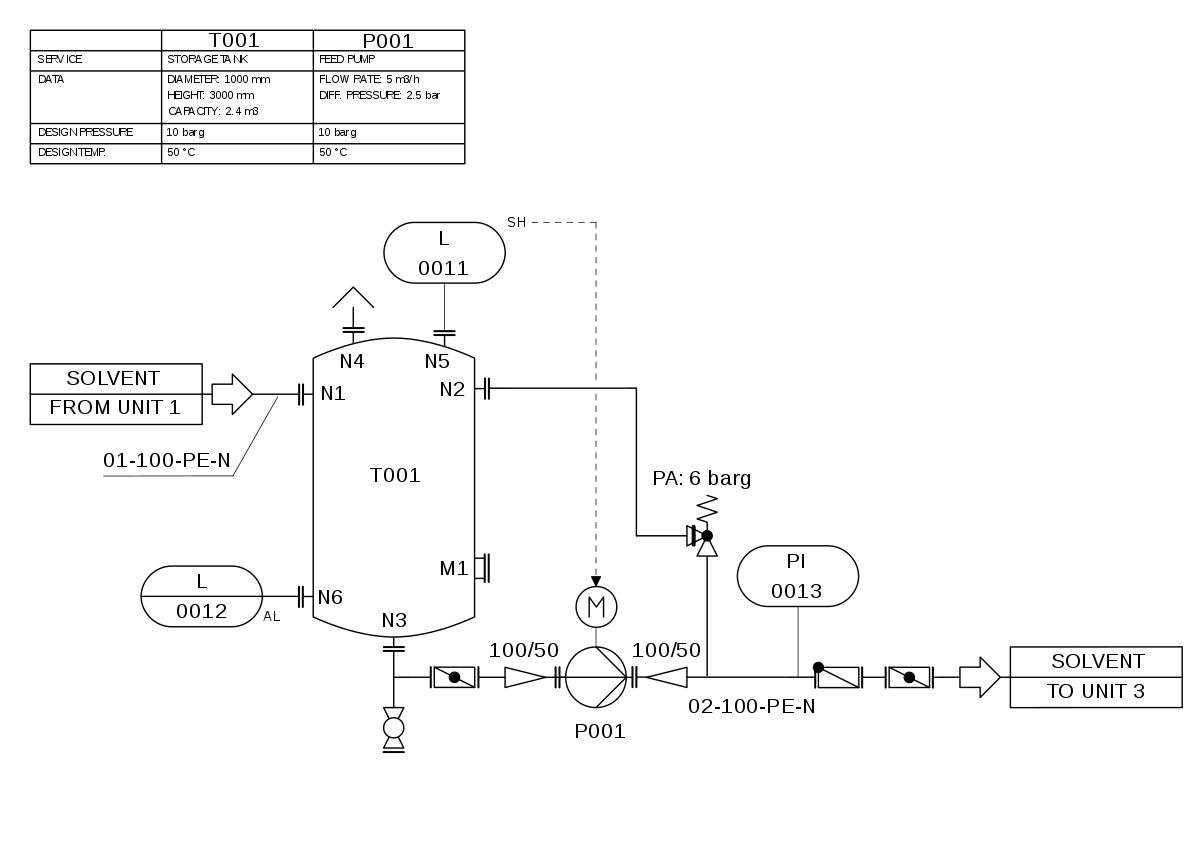
P&ID will contain Equipment number, Equipment Name, Process and Utility piping, Piping size and classification, Instrumentation details like Transmitters, Control valves with their numbers, Control input and output, Annunciation input, SIS input, solenoid valves, On-off valves, Motorised valves, Relief valves, All Mechanical valves Miscellaneous items like strainers, Vents, drains, Silencers, standpipes etc, Vendor items and interfaces, Equipment design pressure, Temperature and Material of Construction, Free draining requirements etc. P&ID will also have general notes that will assist during Detailed Engineering, Erection and Commissioning phase. Though it is not an exhaustive list, Our P&ID Check list in the trailing part of this post will help you to explore in detail about Piping and Instrumentation Diagrams.
P&ID will not contain Operating parameters, Equipment elevation details, Elbows, MTO, etc. It is not drawn to scale and hence geometric accuracy can not be expected out of P&ID.
P&ID Symbols
The instrumentation symbols used in P&ID are as per ISA-S5.1 standard – Instrumentation Symbols and Identification. For Symbols of chemical apparatus and equipment normally ISO, JIS, DIN or PIP standards are followed.

What are the Softwares available to make P&ID?
There is some renowned P&ID software available that can be used online and offline. It saves time in creating a P&ID with the help of simple user-friendly tools available in them. Some of them are,
Autocad is one of the worlds leading design and drafting software used by many of the Chemical Process Design companies for preparing P&ID. 2D and 3D design drawings also can be made out of it.
MS-Visio is very useful offline software for Chemical Engineers to prepare PFD, P& ID and other diagrams in a simple way by just dragging and dropping the symbols.
Lucidchart is an online software for preparing P&I diagrams in a fast manner. Anyone can make the drawing with a drag and drop option. This simple and efficient software also has the functionality to import and export from MS- Visio.
P&ID Review Checklist
Chemical Engineer must review the P&ID before finalizing them for implementation. Our exhaustive Excel P&ID Review Checklist helps to review the P&ID to make it fit based on Safety, Erection, Commissioning and Operation aspects.
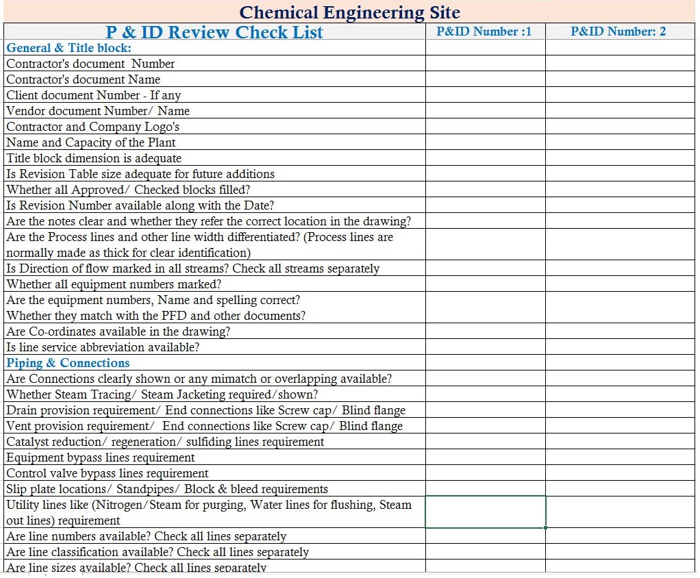

Download the P&ID Review Checklist as Excel file
If you find anything missing in our checklist, feel free to mail to us so that we will add them.
Get unlimited access to 5,000+ magazines, newspapers and curated premium stories at flat 55% off
