Cooling Tower Efficiency Calculation is described in this article. Cooling Tower plays a major role in Chemical Process Industry. They reject process heat from the cooling water to atmosphere and keep the water cool. The performance of the cooling tower depends on various parameters like Range & Approach. We shall see those terminologies in Detail.
Cooling Tower Approach
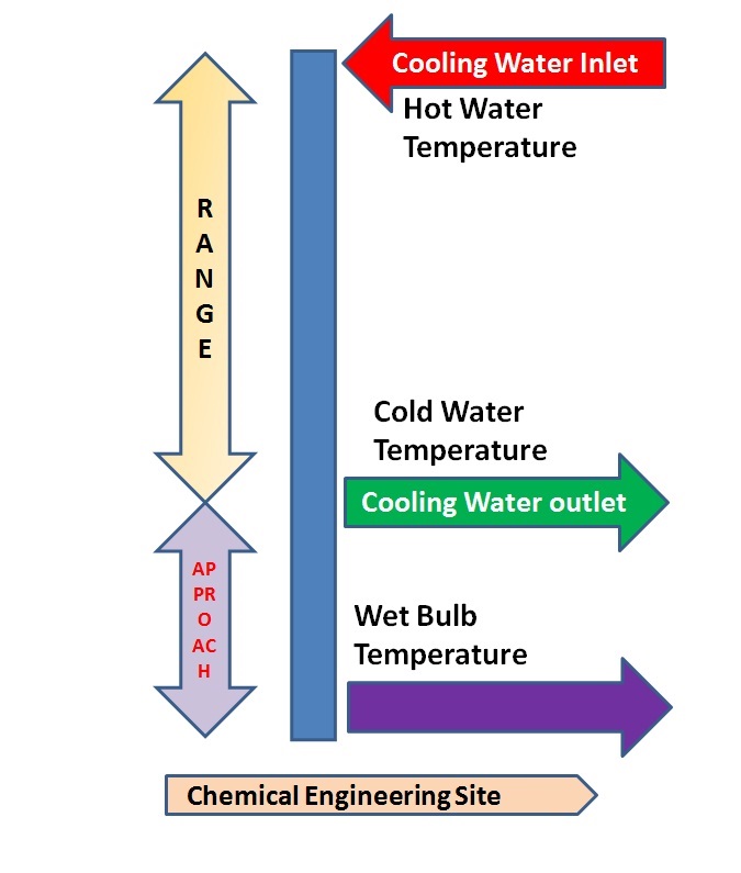
The difference between the Cold Water Temperature (Cooling Tower Outlet)
And ambient Wet Bulb Temperature is called as Cooling Tower Approach.
Approach = Cold Water Temperature – Wet Bulb Temperature
Cooling Tower approach is the better indicator of the performance.
Cooling Tower Range
The difference between the Hot Water Temperature (Cooling Tower Inlet) Temperature and Cold water (Cooling Tower Outlet) temperature is called Cooling Tower Range.
Range = Hot Water Temperature – Cold Water Temperature

Cooling Tower Efficiency Calculation
The calculation of cooling tower efficiency involves the Range and approach of the cooling Tower. Cooling tower efficiency is limited by the ambient wet bulb temperature. In the ideal case, the cold water temperature will be equal to the wet-bulb temperature. This is practically not possible to achieve. This requires very large tower and results in huge evaporation and windage or drift loss resulting in a practically not viable solution. In practice, the cooling tower efficiency will be in between 70 to 75%.
Cooling Tower Efficiency =
(Hot Water Temperature – Cold water Temperature) x 100/
(Hot Water Temperature – Wet bulb temperature)
Or Simply
Cooling Tower Efficiency = Range/ (Range + Approach) x 100
In summer the ambient air wet bulb temperature raises when compared to winter thus limiting the cooling tower efficiency.
Other Cooling Tower Calculations
This includes determination of cycle of concentration, Evaporation loss, Drift or Windage Loss, Blow down water requirement makeup water requirement.
Cycle of Concentration
The cycle of concentration is a dimensionless number. It is a ratio between parameter in Cooling Water to the parameter in Makeup water. It can be calculated from any the following formulae.
COC= Silica in Cooling Water / Silica in Makeup Water
COC = Ca Hardness in Cooling Water/ Ca Hardness in Makeup water
COC = Conductivity of Cooling Water / Conductivity of Makeup water
The cycle of concentration normally varies from 3.0 to 7.0 depending on the Process Design. It is advisable to keep the Cycle of concentration as high as possible to reduce the makeup water requirement of the cooling tower. At the same time, the higher cycle of concentration increases the dissolved solids concentration in circulating cooling water which results in scaling and fouling of process heat transfer equipment.
Draw off or Blowdown
As the cooling water circulates the cooling tower part of water evaporates thereby increasing the total dissolved solids in the remaining water. To control the Cycle of Concentration blow down is given. Blowdown is the function of Cycle of concentration. Blowdown can be calculated from the formula:
B = E/ (COC-1)
B = Blow Down (m3/hr)
E = Evaporation Loss (m3/hr)
COC = Cycle of Concentration. Varies from 3.0 to 7.0 depending upon Manufactures Guidelines
Evaporation Loss Calculation
Evaporation Loss in the cooling tower is calculated by the following empirical equation.
E = 0.00085 x R x 1.8 x C
E = Evaporation Loss (m3/hr)
R= Range
C = Circulating Cooling Water (m3/hr)
(Reference: Perry’s Chemical Engineers Hand Book )
Alternatively, The Evaporation loss can be calculated from the heat balance across the cooling tower. The amount of heat to be removed from Circulating water according to Q = m Cp DT is C x Cp x R . The amount of heat removed by evaporative cooling is Q = m x Hv is E x HV
On Equating these two, we get
E = C x R x Cp / HV
E = Evaporation Loss in m3/hr
C= Cycle of Concentration
R= Range in °C
Cp = Specific Heat = 4.184 kJ / kg / °C
HV = Latent heat of vaporization = 2260 kJ / kg
Windage or Drift Loss Calculation
Drift loss of the cooling tower is normally provided by the cooling tower manufacturer based on the Process design. If it is not available it may be assumed as
For Natural Draft Cooling Tower D = 0.3 to 1.0 * C /100
For Induced Draft Cooling Tower D = 0.1 to 0.3 * C /100
For Cooling Tower with Drift Eliminator D = 0.01* C /100
Cooling Tower Mass Balance – makeup water
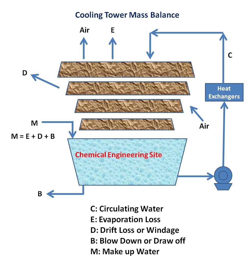

Cooling tower mass balance gives an idea about make-up water requirement. Cooling Tower Makeup has to substitute the water losses resulting from Evaporation, Windage and Blowdown.
M = E + D + B
M = Make up water Requirement in m3/hr
B = Blow Down in m3/hr
E = Evaporation Loss in m3/hr
D = Drift Loss in m3/hr
Have you learned about Cooling Tower Calculations? It’s time to test your knowledge on Cooling towers. Take our Online Quiz on Cooling towers now.
More Articles of Chemical Engineering Site:
Test Your knowledge on Steam Turbines – Online Quiz
Test Your knowledge on Boilers – Online Quiz
Piping and Instrumentation Diagram – P&ID – With Excel Checklist
Test Your knowledge on Confined Space – Online Quiz