Introduction
Heat exchangers are the workhorses of process industries, facilitating energy transfer between fluids in countless applications – from condensing steam in power plants to preheating crude oil in refineries. For process engineers, the ability to size heat exchangers correctly is crucial for ensuring efficiency, safety, and cost-effectiveness.
This step-by-step guide provides a practical methodology for sizing heat exchangers, with references to industry standards (like TEMA and API) and common practices in chemical and process engineering.


1. Define the Process Requirements
Before any calculations, clearly outline the design basis:
- Type of heat exchanger: Shell-and-tube, plate, air-cooled, spiral, etc.
- Duty: Heating, cooling, condensation, vaporization.
- Process fluids: Identify hot and cold streams.
- Operating conditions: Flow rates, inlet/outlet temperatures, pressures.
- Constraints: Space limitations, pressure drop allowances, fouling tendencies.
2. Determine Heat Duty (Q)
The first step is to calculate the heat load:


3. Select Flow Arrangement
Common configurations:
- Counterflow: Maximum heat transfer, higher efficiency.
- Parallel flow: Simpler but less efficient.
- Crossflow: Common in air-cooled exchangers.
- Mixed arrangements: Used for special duties.
The choice affects the log mean temperature difference (LMTD).
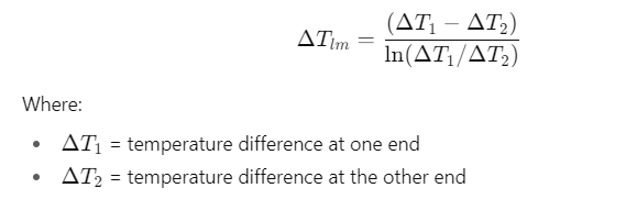
4. Calculate Log Mean Temperature Difference (LMTD)
The driving force for heat exchange is the temperature difference:

Apply correction factors (F) for multi-pass or crossflow arrangements.
5. Estimate Overall Heat Transfer Coefficient (U)
The overall heat transfer coefficient depends on:
- Fluid properties (viscosity, conductivity).
- Heat transfer coefficients (hi, ho).
- Fouling factors (from TEMA standards).
- Wall resistance of tubes/plates.
Typical values (W/m²·K):
- Gas-to-gas: 10–50
- Liquid-to-liquid: 200–1000
- Condensation: 1000–6000
- Boiling: 2000–10,000
6. Determine Required Heat Transfer Area (A)
The fundamental design equation is:

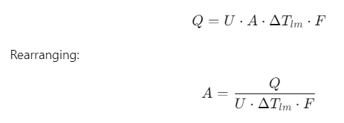
- A = surface area (m²)
- F= correction factor
7. Mechanical Design Considerations
Once the required area is known, translate it into mechanical details:
- Number of tubes/plates.
- Tube length and diameter.
- Shell diameter.
- Pass arrangements.
- Baffles for shell-side flow.
Refer to TEMA (Tubular Exchanger Manufacturers Association) for mechanical standards.
8. Check Pressure Drop
Process engineers must ensure that pressure drop is within allowable limits:
- Tube-side and shell-side pressure drops are calculated using fluid dynamics correlations.
- Excessive drop increases pumping costs and may affect process performance.
9. Fouling and Safety Margins
- Add fouling resistances as per TEMA standards.
- Provide 15–25% design margin in heat transfer area to account for uncertainties.
- Ensure materials of construction resist corrosion and fouling tendencies.
10. Verification with Software Tools
Modern design uses simulation tools:
- Aspen EDR, HTRI, Aspen HYSYS, COMSOL.
- These refine manual calculations, provide detailed rating, and optimize geometry.
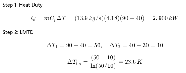
Example Calculation
Problem Statement: Cool 50,000 kg/h of hot water from 90°C to 40°C using cooling water entering at 30°C and leaving at 40°C in a counterflow shell-and-tube exchanger.


Best Practices for Heat Exchanger Sizing
- Always validate assumptions with actual plant data.
- Use conservative fouling factors for dirty services.
- Optimize velocity to balance heat transfer vs. pressure drop.
- Consider alternative technologies (plate exchangers, air coolers).
- Perform lifecycle cost analysis (energy + maintenance).
Conclusion
Heat exchanger sizing is a blend of science and engineering judgment. By following a step-by-step methodology—starting from process data, calculating duty, estimating LMTD, U-values, and required area—engineers can design reliable and efficient exchangers. Advanced simulation tools complement this process, but fundamental understanding remains essential.
Final Thought: Heat exchangers are not just pieces of equipment—they are energy managers of the chemical industry. Proper sizing ensures sustainability, cost savings, and operational excellence.