Introduction to Pretreatment in Desalination
Pretreatment refers to all the physical, chemical, and sometimes biological processes applied to the feedwater before it enters the main desalination units (such as RO membranes or thermal flash evaporators). The main objective is to remove contaminants—such as particulates, colloids, microorganisms, dissolved organics, and scale-forming minerals—that could otherwise foul, scale, or damage downstream desalination modules, especially delicate membranes.
Through efficient pretreatment, plants achieve better operational stability, reduced downtime, longer equipment life, and improved water quality that complies with regulations and end-user expectations. Pretreatment also mitigates environmental and economic costs associated with maintenance, chemical cleaning, and energy consumption.
Why Pretreatment is Essential?
Desalination plants are confronted with highly variable raw water quality. Feedwater may contain sand, silt, clay, organics, algae, bacteria, viruses, heavy metals, and a range of dissolved and suspended materials. These can lead to:
- Fouling of RO membranes (blocking pores, reducing flux).
- Scaling from precipitation of dissolved salts (e.g., calcium carbonate, silica).
- Biofouling due to microbial growth and biofilm formation.
- Chemical attack or oxidation, which degrades membrane or heat exchanger material.
If such contaminants reach the desalination core process (membranes or distillation modules), they can cause irreversible damage, elevate operating costs, and reduce product water quality. Thus, designing a robust pretreatment system is considered mission-critical.
Overview of Pretreatment Processes and Approaches
Pretreatment can be broadly categorized into:
- Physical Methods: Screening, filtration, and sedimentation.
- Chemical Methods: Coagulation, flocculation, disinfection, anti-scalant dosing, pH adjustment.
- Membrane-based Methods: Microfiltration (MF), ultrafiltration (UF), sometimes nanofiltration (NF).
- Hybrid Systems: Combinations of above tailored to specific feedwater characteristics.
The selection depends on raw water quality, plant size, location, operational philosophy, and cost considerations.
The Pretreatment Sequence: A Stepwise Breakdown
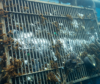
1. Intake and Initial Screening
The journey starts at the intake. Intake and Initial Screening in desalination plants is the first and crucial step where seawater or brackish water is extracted from the source with minimal environmental impact and conveyed to the plant. The intake system typically includes physical structures such as offshore or onshore inlet facilities, intake pipes, and pumps designed to reliably provide the required volume of water while minimizing entrainment and impingement of marine life.
Initial screening involves coarse screens or bar racks that remove large debris like seaweed, plastics, and marine organisms from the incoming water to protect pumps and downstream equipment from damage and clogging. The screened water is then transported to the pretreatment stage for further purification.
Key design considerations for intake and screening include site-specific oceanographic and environmental conditions, proper location with adequate depth, avoidance of sediment disturbance, and use of materials resistant to corrosion. Well-designed intake systems are vital for stable plant operation, as intake problems contribute heavily to unscheduled downtime in desalination plants.
Two main types of intakes are:
- Open intakes: Direct extraction from the ocean using offshore structures and pipelines.
- Subsurface intakes: Use of beach wells or infiltration galleries to draw water from below the seabed, reducing environmental impact by minimizing marine life entrainment.
This first step is essential to ensure that large solids and debris do not enter the system, thereby safeguarding equipment and ensuring efficient subsequent pretreatment and desalination processes.

2. Chemical Addition: Coagulation and Flocculation
Fine suspended and colloidal particles—often invisible to the naked eye—cannot be removed by screening alone. Coagulation and flocculation are essential chemical processes used in the pretreatment of feedwater in desalination plants to remove suspended solids, colloids, and organic materials that cause fouling and scaling in downstream equipment.
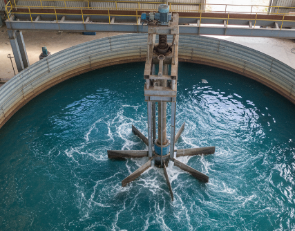
Coagulation
Coagulation is the initial step where chemicals called coagulants (commonly ferric chloride, aluminum sulfate, , or other metal salts) are added to the water. These coagulants carry charges opposite to the negatively charged suspended particles in the water. By neutralizing these charges, coagulation destabilizes the suspended particles, enabling them to come closer and stick together into small aggregates called microflocs, which are not visible to the naked eye. Effective coagulation requires rapid and high-energy mixing with the help of high speed agitators to evenly disperse the coagulant and maximize particle collisions. If coagulation is insufficient, particles remain dispersed and settle poorly in subsequent stages.
Flocculation
Following coagulation, flocculation is a gentler mixing process that encourages these microflocs to collide and grow into larger, visible flocs (pinflocs and macroflocs). Flocculants—typically long-chain polymers (natural or synthetic)—may be added to bridge and strengthen these flocs, increasing their size, weight, and settling rate. Proper control of mixing intensity with the help of slow speed agitator during flocculation is crucial; too vigorous mixing can shear the flocs causing them to break apart, while too gentle mixing may not promote sufficient collisions. Flocculation sets the stage for efficient removal of flocs by sedimentation or filtration in subsequent pretreatment steps.

Importance in Desalination Pretreatment
Together, coagulation and flocculation enhance the removal of suspended solids, turbidity, and organics from seawater or brackish water feed, reducing fouling potential on membranes and improving overall plant performance and longevity. These processes ensure that particles are large enough to be effectively removed in sedimentation tanks, Dissolved Air Flotation (DAF) units, or media filters, thus protecting the delicate reverse osmosis membranes critical to desalination.
In short
- Coagulation neutralizes particle charges to form microflocs.
- Flocculation gently mixes water to grow microflocs into larger flocs.
- Proper chemical dosing and mixing control are essential for effective treatment.
- These processes prevent membrane fouling and improve the efficiency of desalination plants.
This chemical pretreatment is fundamental to maintaining stable and cost-effective operation of modern desalination systems.
3. Clarification: Sedimentation and Floatation
Clarification in desalination pretreatment involves removing suspended solids and impurities to protect downstream processes. It includes both sedimentation and flotation methods, each with specific types and equipment.
Sedimentation
Sedimentation is a gravity-based process where suspended particles (flocs formed during coagulation and flocculation) settle to the bottom of a tank due to their weight. This reduces turbidity and total suspended solids (TSS) before further treatment.
Types of Sedimentation
- Plain Sedimentation: Particles settle based on individual size and density under gravity without chemical aids.
- Flocculation Sedimentation: Uses coagulation-flocculation chemicals to form larger, heavier flocs that settle faster.
- Hindered or Zone Settling: Occurs at high solids concentration where particles settle as a mass or blanket.
- Discrete Settling: Individual particles settle without interaction.
Sedimentation Equipment
- Rectangular Sedimentation Basins: Long tanks with horizontal flow, allowing particles to settle as water flows through.
- Circular (Radial Flow) Clarifiers: Large circular tanks where water enters centrally; sludge is scraped from conical bottoms.
- Inclined Plate or Tube Settlers: Increase settling area by redirecting flow upward through inclined surfaces.
- Solids Contact Clarifiers: Combine coagulation, flocculation, and sedimentation in one unit with sludge recycling.
Sedimentation tanks typically have sludge collection and removal systems like scrapers or augers to manage settled solids effectively.
Lamella Clarifier
A Lamella Clarifier is a type of sedimentation tank used in water and wastewater treatment to remove suspended solids from liquids by enhancing settling efficiency. It consists of a series of closely spaced, inclined plates (called lamella plates) arranged at an angle (usually 45 to 60 degrees) inside a compact tank. These plates create multiple narrow channels that increase the effective settling surface area while reducing the tank footprint.
How Lamella Clarifier Works?
Raw or preconditioned water enters the clarifier and flows upward between the inclined plates. Suspended particles settle onto the plate surfaces due to gravity as the water velocity is slowed down. The solids then slide down the plates by gravity into a sludge collection hopper at the bottom. The clarified water exits from the top of the tank through an overflow weir.
When is a Lamella Clarifier better than a conventional clarifier?
- Space constraints exist: Lamella clarifiers require significantly less footprint (up to 90% reduction) due to inclined plate design, making them suitable for compact sites or retrofits.
- Higher flow rates are needed: Increased effective settling surface area allows handling higher flow with smaller tank volume.
- Faster settling of fine or low-density particles is required: The inclined plates shorten settling distance and improve removal efficiency for slow-settling solids.
- Installation costs and land acquisition are limited: Smaller tanks reduce construction and land costs.
- Improved sludge handling and maintenance: Sludge collects efficiently on inclined plates, facilitating easier removal compared to large conventional tanks.
- Pretreatment for membrane systems: Lamella clarifiers provide higher water clarity critical for protecting delicate downstream membranes in desalination plants.
In contrast, conventional clarifiers may be preferred where large open land is available and simpler, lower-cost tanks suffice without stringent space or flow requirements.
Hence, lamella clarifiers excel in space-limited, high-performance, and modern treatment applications demanding compact, efficient clarification.
Flotation
Flotation separates suspended particles by attaching air bubbles to them, making them buoyant so they float to the surface for removal. It is effective for light solids, algae, oils, and grease that are difficult to settle.
Types of Flotation
- Dissolved Air Flotation (DAF): Air is dissolved under pressure into water and released at atmospheric pressure, forming microbubbles that attach to particles.
- Induced Gas Flotation (IGF): Gas bubbles are mechanically generated and introduced into the water.
- Electroflotation: Uses electrolytic gas generation to form microbubbles.
Flotation Equipment
- DAF Units: Include pressurized saturators, release tanks, and skimming mechanisms to remove floated solids.
- Flotation Basins: Tanks designed for slow water flow to allow bubble-particle attachment and surface skimming.
- Skimmers and Scrapers: Remove floated sludge from the water surface for disposal.
DAF is widely used in seawater pretreatment because it efficiently removes algae and fine particles that sedimentation may miss, though it requires more energy.
In Short
| Process | Principle | Common Equipment | Applications in Pretreatment |
|---|---|---|---|
| Sedimentation | Gravity settling of flocs | Rectangular basins, circular clarifiers, inclined plate settlers Lamella clarifier | Removal of heavier suspended solids and flocs |
| Flotation | Air bubbles lift particles | DAF units, flotation basins, skimmers | Removal of algae, oils, grease, light solids |
Both clarification methods are crucial pretreatment steps to reduce solids load and biofouling potential, optimizing membrane life and system efficiency in desalination plants.
4. Media Filtration
Media filtration is a water treatment process that removes suspended solids, particulates, and some organic matter. Clarified water passes through media filters (often sand, anthracite, or granular activated carbon). These filters polish the water, removing particles down to a few microns. Activated carbon further adsorbs organic compounds and residual chlorine. Dual or multi-media filters improve filtration rates and reduce the silt density index (SDI), a key metric in RO membrane protection.
How Media Filtration Works?
Water flows through a bed of filtration media at a controlled slow rate. Different media layers trap particles by multiple mechanisms including physical straining, sedimentation, adsorption, and biological degradation. The most common multi-layered filter media setup includes:
- Top Layer: Coarse anthracite or coal to remove larger particles and distribute water evenly.
- Middle Layer: Fine sand to trap smaller particles and suspended solids.
- Bottom Layer: Garnet or gravel to support upper layers and prevent media washout.
Filtration progressively removes turbidity, total suspended solids (TSS), and particles that could clog or foul downstream systems. The resulting filtered water is clearer and meets quality standards required for post-treatment or use.
Types of Media Filtration
- Single Media Filters: Use a single layer of sand or anthracite.
- Dual Media Filters (DMF): Typically layers of anthracite over sand, improving filtration efficiency and run time.
- Multimedia Filters: Several layers (e.g., anthracite, sand, garnet, activated carbon) targeting a broader range of particle sizes and contaminants.
- Pressure Filters: Filtration occurs inside pressurized vessels, suitable for high flow rates and compact installations.
- Gravity Filters: Utilize gravity flow through media, typically in large open beds.
Media & Its Role
Sand Layer
- Removal Efficiency: Sand filters typically remove 70% to 90% of turbidity and suspended solids under optimal conditions.
- Characteristics: Sand grains have a specific gravity of about 2.65 and an effective size usually between 0.35 to 0.60 mm. Fine sand provides deeper filtration and retains smaller particles, but clogging can occur faster near the surface.
- Role: Acts as the main filtering medium, removing fine particles and suspended solids.
Garnet Layer
- Removal Efficiency: Garnet, used as a bottom support layer, aids in removing residual fine particles and supports the sand layer. It contributes to enhancing separation efficiency.
- Characteristics: Garnet has a higher specific gravity (~4.0-4.2), which helps keep it at the bottom during backwashing. Typical effective size ranges around 0.2 to 0.4 mm.
- Role: Provides graded filtration and supports overlying media, increasing overall filter bed stability and efficiency.
Coal (Anthracite) Layer
- Removal Efficiency: The coarse anthracite coal layer removes larger particles, distributing flow evenly and extending filter run times by reducing premature clogging of the finer sand beneath. It contributes to total suspended solids removal efficiently.
- Characteristics: Anthracite coal has lower specific gravity (1.35 to 1.75) and is used in sizes from about 0.6 to 1.5 mm, placed as the top layer.
- Role: Acts as a pre-filter layer, preventing excessive load on finer sand below and enabling longer filter run times.
In Short
| Media | Specific Gravity | Typical Grain Size (mm) | Removal Efficiency for Turbidity/Suspended Solids | Key Role |
|---|---|---|---|---|
| Sand | ~2.65 | 0.35 – 0.60 | 70% – 90% | Fine particle filtration |
| Garnet | ~4.0 – 4.2 | 0.20 – 0.40 | Supports filtration, helps fine particle removal | Bottom layer media support |
| Anthracite | 1.35 – 1.75 | 0.6 – 1.5 | Removes coarse particles, extends run time | Top coarse media layer |
Equipment Used
- Filter Tanks: Made of steel, fiberglass, or concrete, sized according to flow rate and application.
- Distribution and Collection Systems: Ensure even distribution of influent water and collection after filtration to avoid channeling.
- Backwash Systems: Reverse flow to clean and regenerate filter media periodically by removing trapped solids.
- Automated Control Systems: Monitor pressure differentials and automate backwashing cycles for optimal performance.
In summary, media filtration is a versatile, cost-effective filtration technique employing granular media beds to remove suspended solids, crucial for water purification and desalination pretreatment.
5. Advanced Membrane Filtration (MF/UF/NF)
In recent years, there’s been a strong shift to membrane-based pretreatment. Advanced membrane filtration refers to a group of membrane-based separation processes used for water treatment, leveraging semipermeable membranes to remove various contaminants based on size and charge. The main types in this category are Microfiltration (MF), Ultrafiltration (UF), and Nanofiltration (NF), each targeting progressively smaller particles and molecules.
Microfiltration (MF)
- Pore Size: Typically 0.1 to 10 microns.
- Removal Targets: Suspended solids, bacteria, algae, protozoa, and most particulate matter.
- Applications: Used primarily for removing larger particles and microorganisms; often a pretreatment step before UF or NF/RO.
- Membrane Types: Hollow-fiber or flat-sheet membranes.
- Limitation: Does not remove dissolved salts or smaller organic molecules.
Ultrafiltration (UF)
- Pore Size: Approximately 0.001 to 0.1 microns.
- Removal Targets: Colloids, viruses, proteins, emulsified oils, and large organic molecules.
- Applications: Drinking water purification, wastewater treatment, and as an effective pretreatment to reverse osmosis to prevent membrane fouling.
- Membrane Types: Typically polymeric hollow fibers or spiral wound.
- Advantages: High removal efficiency of biological contaminants and macromolecules with moderate energy consumption.
Nanofiltration (NF)
- Pore Size: Around 0.0001 to 0.001 microns.
- Removal Targets: Multivalent ions (calcium, magnesium), large organic molecules, some dissolved solids but not monovalent ions like sodium or chloride.
- Applications: Softening water, removing heavy metals and organic compounds, partial desalination, and wastewater reuse.
- Membrane Types: Spiral wound primarily.
- Advantages: Operates at lower pressure than reverse osmosis, more energy efficient for specific ion and organic removal.
Comparison of MF, UF & NF Membrane Pore Size
| Membrane Type | Pore Size (Microns) | Removes | Common Applications |
|---|---|---|---|
| Microfiltration (MF) | 0.1 – 10 | Suspended solids, bacteria, algae | Water pretreatment, particle removal |
| Ultrafiltration (UF) | 0.001 – 0.1 | Viruses, colloids, proteins | Biological contaminant removal, RO pretreatment |
| Nanofiltration (NF) | 0.0001 – 0.001 | Multivalent ions, organics | Water softening, heavy metal removal |
Energy and pressure requirements vary significantly among Microfiltration (MF), Ultrafiltration (UF), and Nanofiltration (NF) membranes due to their pore sizes and the nature of filtration.
Pressure Requirements
- Microfiltration (MF):
Operates at low pressures, typically around 1 to 3 bar (15 to 45 psi) because larger pore sizes allow easier water flow. This makes MF energy-efficient for removing suspended solids and microorganisms. - Ultrafiltration (UF):
Requires moderate pressures, ranging from about 1.5 to 4 bar (20 to 60 psi), due to its finer pores which restrict flow more than MF. UF balances good removal performance with reasonable energy use. - Nanofiltration (NF):
Operates at higher pressures, usually 3 to 7 bar (45 to 100 psi), since smaller pores and membrane surface charge require more force to push water through. NF consumes more energy but achieves partial desalination and removes multivalent ions.
Energy Consumption
- MF: Typically consumes around 0.01 to 0.04 kWh per cubic meter due to low pressure and cross-flow velocity requirements.
- UF: Slightly higher, ranging from 0.02 to 0.08 kWh/m³ because of increased pressure and membrane resistance.
- NF: Energy use is higher, approximately 0.1 to 0.3 kWh/m³, reflecting the need for greater pressures and tight filtration.
Comparison of MF,UF & NF energy requirement
| Membrane Type | Operating Pressure (bar) | Typical Energy Consumption (kWh/m³) | Filtration Fineness |
|---|---|---|---|
| Microfiltration (MF) | 1 – 3 | 0.01 – 0.04 | Larger particles |
| Ultrafiltration (UF) | 1.5 – 4 | 0.02 – 0.08 | Viruses, colloids |
| Nanofiltration (NF) | 3 – 7 | 0.1 – 0.3 | Multivalent ions, organics |
Lower pressure requirements make MF and UF suitable for pretreatment steps, with NF acting as a middle ground before reverse osmosis in desalination plants where higher quality permeate is needed but at higher energy costs. Energy and pressure requirements vary significantly among Microfiltration (MF), Ultrafiltration (UF), and Nanofiltration (NF) due to differing membrane pore sizes and filtration mechanisms.
- Microfiltration (MF) typically operates at low pressures around 1–3 bar (15–45 psi), requiring minimal energy—about 0.01 to 0.04 kWh per cubic meter—due to its larger pore size that allows easier water flow.
- Ultrafiltration (UF) operates at moderate pressures, approximately 1.5–4 bar (20–60 psi), consuming slightly higher energy, roughly 0.02 to 0.08 kWh/m³, as the finer pores restrict flow more than MF.
- Nanofiltration (NF) requires higher operating pressures, generally 3–7 bar (45–100 psi), and consequently more energy (around 0.1 to 0.3 kWh/m³), reflecting its tighter filtration that removes multivalent ions and larger organics.
This increasing trend in pressure and energy use correlates with membrane pore size reduction and filtration fineness, making MF and UF suitable for pretreatment steps with lower energy costs, while NF serves more selective filtration needs closer to reverse osmosis level at higher energy expenditure.
Role of in Desalination Pretreatment
Advanced membrane filtration (MF/UF/NF) is used as part of pretreatment in desalination plants to provide high-quality feedwater by removing suspended solids, microorganisms, colloids, and some dissolved organics. This lessens fouling risk in reverse osmosis membranes, prolonging lifespan while improving efficiency and reducing chemical consumption.
In short, MF, UF, and NF are critical membrane filtration technologies with increasing filtration fineness, serving diverse roles in water treatment and desalination pretreatment to ensure reliability and water quality with slight increase in energy consumption.
6. Cartridge Filters
Prior to the desalination unit (e.g., RO), water typically passes through fine cartridge filters (1–5 μm) that trap any residual particulate matter, ensuring the highest possible feed quality and safeguarding the integrity of expensive reverse osmosis membranes. Cartridge filters are designed to remove suspended solids, sediments, and impurities by forcing water through a cylindrical filter media housed within a cartridge. The cartridge acts as the heart of the filtration unit and is inserted inside a filter housing.
Types of Cartridge Filters
- Surface Filters:
- Operate by trapping contaminants on the outer surface of the filter media.
- Suitable for particulates of uniform size.
- Examples: Pleated filters (polypropylene, cellulose), cellulose cartridge filters.
- Usually have faster flow rates but clog quickly as particles accumulate on the surface.
- Depth Filters:
- Contaminants penetrate into the depth of the filter media, captured throughout multiple layers.
- Effective for a wide range of particle sizes and high dirt-holding capacity.
- Examples: String wound cartridges, ceramic filters, sintered metal filters.
- Longer lifespan, slower flow rate due to tortuous path for fluids.
Common Materials of Construction (MOC)
- Polypropylene (PP): Most common for spun bonded, pleated, and wound filter cartridges; chemical resistant, inexpensive, suitable for sediment removal and many industrial uses.
- Cellulose: Used in surface filters; biodegradable but less chemically resistant.
- Polytetrafluoroethylene (PTFE): For highly corrosive and sterilization applications, offers excellent chemical resistance.
- Stainless Steel: Used for reusable cartridges in applications requiring high mechanical strength and cleaning.
- Ceramics and Sintered Metals: For high-temperature, abrasive, or highly purified streams.
Cartridge Filter Types Based on Construction
| Filter Type | Key Features | Typical Applications |
|---|---|---|
| Spun Bonded | Depth filter, graded density, high dirt capacity | Pre-filtration, sediment removal |
| Pleated | Large surface area, surface filtration | High flow rate, fine particle removal (0.2–70 micron) |
| String Wound | Depth filtration, resilient to chemicals | Industrial water, pool filtration, oil filtration |
| Ceramic | High temperature, chemically resistant | Pharma, food, sterilized water |
Important Considerations
- Cartridge filters vary widely from disposable single-use types to reusable industrial-grade filters.
- Filtration ratings range from sub-micron (0.2 micron) to several hundred microns depending on application.
- Cartridge filters can be configured as Single Open End (SOE) or Double Open End (DOE).
- Maintenance includes regular replacement, cleaning (for reusable types), and monitoring the pressure drop across the filter.
In Short
Cartridge filters play a critical role in desalination pretreatment and general water purification by removing particulates and protecting downstream sensitive equipment. The selection of cartridge filter type and MOC depends on feedwater quality, chemistry, required filter life, and operational conditions.
7. Chemical Conditioning
- Disinfection: Chlorine or alternative disinfectants are dosed to suppress biofouling in the pre-treatment stage. Dechlorination (e.g., using sodium bisulfite) is then performed before RO, as residual chlorine would damage membranes.
- Anti-scalants: Dosed to prevent precipitation of calcium, magnesium, silica, and other minerals.
- pH Adjustment: The pH of seawater is modified—commonly lowered—to prevent scaling and to optimize the overall pretreatment process.
Key Water Quality Parameters in Pretreatment
Here are concise one-line explanations for each parameter used in desalination pretreatment monitoring:
- Turbidity: Measures the cloudiness of water due to suspended particles, indicating potential fouling risks.
- Silt Density Index (SDI): Assesses the fouling potential of feedwater by measuring the rate at which a filter is blocked by particulates.
- Total Suspended Solids (TSS): Quantifies the total amount of solid particles suspended in water, relevant to filter loading and fouling.
- Dissolved Organic Carbon (DOC): Indicates the amount of organic molecules dissolved in water, which may contribute to membrane fouling and biofilm formation.
- Total Dissolved Solids (TDS): Reflects the sum of all dissolved minerals and salts in water, important for salinity measurement and membrane loading.
- Conductivity: Represents the ability of water to conduct electricity, directly related to the concentration of dissolved ions or salts.
- pH: Measures how acidic or basic the water is, affecting scaling risk, chemical dosing, and membrane performance.
- Temperature: Influences chemical reaction rates, solubility of gases, and membrane permeability, impacting process efficiency.
- Residual Chlorine: Refers to the leftover chlorine after disinfection, which must be minimized before RO to prevent membrane damage.
- Microbiological Counts (cfu/ml or biofilm monitoring): Tracks microbial contamination or biofilm formation, essential for controlling biological fouling.
Target Ranges for Pretreatment
| Parameter | Target Range/Limit | Remarks |
|---|---|---|
| Turbidity | < 0.2 to 1.0 NTU | Lower values reduce membrane fouling risk |
| Silt Density Index (SDI 15) | < 3 to 5 | <3 preferred for reliable RO operation |
| TSS | < 10 mg/L | Limits fouling and protects membranes |
| DOC | As low as possible, < 1.5 mg/L preferred | Minimizes organic fouling |
| TDS | Monitored per source; no strict pretreatment limit, but tracking for process optimization | |
| Conductivity | Stable; varies with raw water source | Sudden spikes may indicate operational issues |
| pH | 6.5–8.5 (feed to RO) | Optimized for anti-scalant efficacy and membrane protection |
| Temperature | < 45°C (<113°F) | High temperatures strain membranes |
| Residual Chlorine | < 0.1 mg/L | Prevents membrane degradation |
| Microbiological Counts | Minimal; biofilm controlled by regular monitoring and biocide dosing | Reduces biofouling risk |
Pretreatment Technology Choices: Conventional vs. Membrane-Based
| Parameter | Conventional Media | Membrane-based (MF/UF) |
|---|---|---|
| Particle removal | Down to ~5–10 μm | Down to 0.01–0.1 μm |
| Biological removal | Limited | Effective (bacteria, some viruses) |
| Organic removal | Variable | Moderate (with PAC dosing) |
| Footprint | Larger | Smaller |
| Operational stability | Moderate | High, but sensitive to fouling |
| Investment cost | Lower | Higher initially |
| O&M costs | Lower, labor intensive | Lower (automation possible) |
| Cleaning requirements | Manual/backwashing | Chemical, periodic cleaning |
| Typical applications | All plant sizes | Recent, large/modern plants |
Membrane-based pretreatment is growing in popularity due to its superior and consistent filtrate quality, especially suited for problematic feedwaters, but requires robust fouling control and periodic chemical cleaning.
Challenges in Pretreatment for Desalination
Despite advances, several challenges must be managed in pretreatment stages:
- Algal Blooms: Harmful algal blooms (HABs) can overload pretreatment systems with organic load, toxins, and fine particulates; DAF and advanced oxidation, with tight monitoring, offer solutions.
- Biofouling: Growth of bacteria and biofilms on filters and membranes leads to frequent cleaning, higher chemical use, and increased costs. Online biofilm monitoring tools, controlled dosing, and periodic backflushing are essential.
- Scaling and Clogging: Inorganic scales (CaCO₃, BaSO₄) can form if not properly conditioned with pH control and anti-scalants.
- Oxidant Residuals: As many membranes are chlorine-sensitive, residual oxidants must be precisely neutralized before the primary desalination units.
- Variability in Feedwater Quality: Coastal environments or rivers can exhibit wide seasonal and event-driven swings in turbidity, organics, and microbe content. Dynamic process control and flexible pretreatment configurations are needed.
Recent Trends and Advancements
- Shift to Membrane Pretreatment: MF and UF technologies increasingly replace traditional media filtration due to smaller footprints, automation, and superior protection for RO membranes.
- Hybrid Approaches: Combining DAF with membrane filtration provides robust protection against organic-rich or algae-laden waters.
- Online Monitoring: Sensors for SDI, biofilm growth, and online turbidity now provide real-time feedback for process optimization.
- Advanced Coagulants: Use of sustainable, biodegradable, or tailor-made polymers to enhance coagulation/flocculation efficiency.
- Digital Transformation & Industry 4.0: Automation platforms can adjust dosing, filter backwash, and process configurations based on real-time water quality data. Integration of cyber-physical systems, IoT, AI, big data, and advanced analytics for autonomous and intelligent decision-making in desalination plants.
- Zero Liquid Discharge (ZLD) Integration: Tighter regulation of brine and chemical waste is driving pretreatment systems to reduce chemical consumption and facilitate ZLD processes.
Environmental and Economic Aspects
Efficient pretreatment enables lower chemical and energy consumption, reduces membrane cleaning frequency, mitigates hazardous discharges, and ultimately lowers the carbon footprint of desalination. However, the choice and operation of pretreatment steps must balance capital expenditure, operational costs, and environmental compliance.
Case Study Snapshots
Large SWRO Plants
In major SWRO (Seawater Reverse Osmosis) plants—such as those in the Middle East, Spain, and Australia—a mix of DAF, dual-media filtration, and MF/UF pretreatment is commonly deployed. These plants have demonstrated plant availability >90% and membrane lifespans exceeding five years when equipped with advanced pretreatment and real-time monitoring.
Small/Remote Plants
For brackish water desalination in remote areas or mobile units, physical-chemical approaches (screening, coagulation-flocculation, followed by cartridge filtration) are often more appropriate due to lower cost, modularity, and lower O&M complexity.
Future Outlook
Pretreatment in desalination plants is an area of active research and industrial innovation. Promising directions include:
- Smart Pre-treatment Modules: Integrated sensors and data-driven algorithms to dynamically adjust process parameters.
- Green Chemistry: Enzyme-based coagulants, plant-extract flocculants, and non-toxic scale inhibitors.
- Enhanced Membrane Materials: Antifouling coatings, improved chemical compatibility, and bioinspired surface designs.
- Resource Recovery: Selective removal and harvesting of valuable minerals from seawater during pretreatment.
- Sustainability by Design: Water-energy nexus optimization, reducing greenhouse emissions and chemical footprints.
As desalination plays an increasingly vital role in global water security, robust and adaptable pretreatment remains central to its sustainability and success.
Conclusion
Pretreatment in Desalination plants is far more than a preliminary filtration step—it is the linchpin of efficient, reliable, and sustainable desalination plant operation. Advances in physical, chemical, and membrane-based pretreatment have helped overcome many of the challenges that once plagued desalination, such as rapid membrane fouling and unreliable water quality. Continued innovation in monitoring, process design, and sustainable chemistry will further drive down costs, minimize environmental impact, and ensure that desalination fulfills its promise as a source of potable water for generations to come.