Introduction
Flow measurement is an essential discipline in process engineering, instrumentation, and fluid mechanics, enabling the quantification of fluid movement in pipelines, open channels, or natural bodies of water. Understanding flow behavior and accurately measuring flow rates are fundamental for optimizing industrial processes, ensuring safety, improving product quality, and enabling precise control in chemical, water treatment, oil & gas, HVAC, and many other sectors.
This article comprehensively covers the basics of flow measurement, starting from fundamental concepts, types of flow quantities, units, and ending with various flow measurement technologies, their working principles, advantages, limitations, and applications.
What Is Flow and Flow Measurement?
Flow refers to the movement of fluid—liquid or gas—through a conduit or an open channel. Fluids in motion possess velocity, and the flow rate is a measure of how much fluid passes through a given cross-sectional area per unit time.
Flow measurement is the process of quantifying the bulk movement of fluid, usually represented as volume flow rate or mass flow rate, depending on the application. It involves using instruments called flow meters which convert the physical parameters of flow into usable data.
Important Flow Quantities
There are three primary measurable flow quantities in fluid mechanics and process control:
- Velocity of the Fluid (v): Measured in meters per second (m/s), velocity is the speed at which fluid particles pass through a specific point.
- Volumetric Flow Rate (Q): The volume of fluid flowing per unit time, measured in units such as cubic meters per second (m³/s), liters per minute (L/min), gallons per minute (GPM), etc.
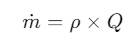
- Mass Flow Rate (ṁ): The total mass of fluid passing a point per unit time, measured in kilograms per second (kg/s), tonnes per hour (t/h), etc.
The relation between these quantities for an incompressible fluid is given by the fundamental equation:

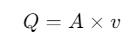
where A is the cross-sectional area perpendicular to the flow. Mass flow rate can be found by multiplying volumetric flow rate by fluid density

Units of Flow Measurement
Flow units depend on the flow quantity being measured:
- Volumetric flow units: Cubic meters per second (m³/s), liters per minute (L/min), gallons per minute (GPM), cubic feet per minute (CFM), etc.
- Mass flow units: Kilograms per second (kg/s), tonnes per hour (t/h), pounds per hour (lb/hr), etc.
- For gases, flow rates are often reported at standard conditions (Standard Temperature and Pressure – STP) due to compressibility effects, expressed as standard cubic meters per hour (Nm³/h or Sm³/h).
Types of Fluid Flow
Understanding the nature of flow is critical for choosing the appropriate measurement technique.
- Laminar flow: Fluid moves in smooth, orderly layers with minimal mixing, typically at low velocities (Reynolds number < 2000).
- Turbulent flow: Flow exhibits irregular fluctuations and mixing; velocity varies over time and space, common in industrial applications (Reynolds number > 4000).
- Transient or unsteady flow: Flow velocity changes with time.
Categories of Flow Measurement
Flow measurement devices are generally classified based on how they measure flow and the principle they leverage:
1. Differential Pressure Flowmeters (Obstruction Type)
These devices measure the pressure drop caused by a constriction or obstruction placed in the flow path. Common types:
- Orifice plates
- Venturi tubes
- Nozzles
The principle is based on Bernoulli’s equation where fluid velocity increases passing through the constriction, causing a pressure drop proportional to the square of flow velocity.
2. Positive Displacement Flowmeters
These meters measure flow by trapping fixed volumes of fluid and counting the number of times the volume is filled. Used primarily for viscous fluids and where direct volume measurement is critical.
Examples include:
- Gear meters
- Piston meters
- Rotary vane meters
3. Velocity Flowmeters
Instead of measuring pressure drop, these meters measure the velocity of fluid to calculate flow. Types include:
- Turbine flowmeters: Use a rotor that spins with fluid velocity; rotational speed proportional to flow velocity.
- Electromagnetic flowmeters: Use Faraday’s law; measure voltage induced by conductive fluid moving through magnetic field; suitable for conductive fluids.
- Ultrasonic flowmeters: Use sound waves traveling with and against flow; measure Doppler shift or transit time difference.
- Vortex flowmeters: Utilize vortex shedding phenomenon behind a bluff body; vortex frequency proportional to flow velocity.
4. Mass Flowmeters
These directly measure mass flow, essential for accurate flow measurement of gases and liquids where density may vary.
- Coriolis flowmeters: Measure mass flow based on the Coriolis force induced by fluid flowing through vibrating tubes.
- Thermal mass flowmeters: Measure flow based on heat dissipation in the fluid.


Principles of Common Flowmeters
1. Orifice Flow meters
Orifice flow meters are differential pressure flow measurement devices that work by constricting fluid flow through a precisely sized hole (orifice) in a thin plate installed inside a pipe.
Working Principle of Orifice flow meters
- Based on Bernoulli’s theorem, as fluid approaches the orifice plate, the flow area is reduced, causing an increase in fluid velocity and a corresponding decrease in pressure.
- This pressure drop is measured between points upstream and downstream of the orifice plate using pressure taps connected to a differential pressure sensor (like a manometer).
- The magnitude of this differential pressure is directly related to the flow rate through the orifice.
- Fluid velocity is highest at the vena contracta, a narrow point downstream of the orifice where the flow cross-section is minimum.
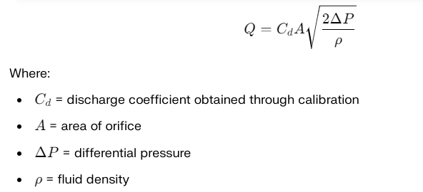
- Using Bernoulli’s equation and the continuity equation, the volumetric flow rate QQQ can be calculated from the measured differential pressure ΔP\Delta PΔP.
Orifice Meter Components
- Orifice Plate: A thin, flat, metal plate with a central circular hole (orifice) installed perpendicular to flow inside the pipe.
- Pipe Sections: Straight inlet and outlet sections where pressure taps are installed for differential pressure measurement.
- Pressure Taps: Upstream and downstream connections to measure pressure difference.
- Differential Pressure Sensor: Converts pressure difference into an electrical signal for flow rate calculation.
Key Formula
This explanation provides a clear overview of the orifice flow meter’s working, construction, and practical considerations based on differential pressure measurement.

Advantages of Orifice flow meters
- Inexpensive and simple design
- Easy to install
- Suitable for liquids, gases, and steam
- Robust and widely used in industry
Limitations of Orifice flow meters
- Causes high permanent pressure loss due to turbulence
- Sensitive to flow disturbances and requires straight pipe lengths for accuracy
- Can clog or corrode affecting accuracy
- Not suitable for dirty or multiphase fluids
Applications of Orifice flow meters
Orifice meters are commonly used in water supply, petroleum, chemical plants, and natural gas industries for monitoring and controlling fluid flow.
2. Venturi Meter
A Venturi meter is a flow measurement device working on the principle of Bernoulli’s equation, which relates fluid velocity and pressure. It measures the flow rate of a fluid flowing through a pipe by creating a differential pressure between two sections.
Construction and Components of Venturimeter
A Venturi meter consists mainly of the following parts:
- Inlet Cylinder: The fluid enters the meter through this cylindrical section matching the pipe’s diameter, ensuring smooth entry.
- Converging Cone: This cone narrows the flow passage, causing the fluid velocity to increase while pressure decreases.
- Throat: The narrowest section of the meter, where the fluid reaches maximum velocity and minimum pressure. The cross-sectional area here is the smallest.
- Diverging Cone: After the throat, the section gradually widens, reducing fluid velocity and allowing pressure to recover.
- Pressure Connections: Openings at the inlet and throat connect to a differential pressure sensor (like a manometer or transmitter) to measure the pressure difference.
- Vent and Drain: Allow for the release of trapped gases and removal of liquids to maintain meter accuracy.
- Inspection Hole and Support: For maintenance and mounting.
Working Principle of Venturimeter
- Fluid flows into the Venturi meter through the inlet cylinder with pressure P1.
- As the cross-sectional area narrows in the converging cone, velocity increases and pressure drops to P2 at the throat.
- This pressure drop (ΔP=P1−P2) is measured using the pressure sensors.
- According to Bernoulli’s equation and the continuity equation, this pressure difference is related to the flow velocity and, hence, the volumetric flow rate.
- The diverging cone helps the fluid regain pressure and kinetic energy with minimal losses.
Key Equations in Venturimeter
From Bernoulli’s principle and continuity:

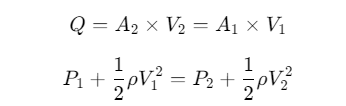
Solving for velocity and flow rate allows determination of flow through pressure difference.
Advantages of Venturimeter
- Low permanent pressure loss due to gradual constriction and recovery.
- Self-cleaning effect reduces fouling.
- Accurate and reliable in various industrial conditions.
- Suitable for large pipes and high flow rates.
Applications of Venturimeter
Venturi meters are widely used in industries such as water supply, wastewater treatment, oil and gas, chemical processing, and power plants due to their robustness and accuracy.
This explanation covers the essential working, parts, and importance of Venturi meters in fluid flow measurement.
3. Electromagnetic Flowmeters
Electromagnetic flowmeters, also known as magmeters, operate based on Faraday’s Law of Electromagnetic Induction. This principle states that when a conductive fluid flows through a magnetic field, it induces an electrical voltage proportional to the fluid’s velocity.
Working Principle of Electromagnetic Flowmeters
- Inside the flowmeter, a magnetic field is generated by coils wrapped around or mounted near the flow tube.
- As the conductive fluid flows through this magnetic field, it acts like a moving conductor cutting through magnetic lines of force.
- This interaction induces a voltage across two electrodes placed perpendicular both to the magnetic field and the flow direction.
- The magnitude of the induced voltage E is directly proportional to:
- The fluid velocity v,
- The magnetic field strength B,
- The length of the conductor l (which equals the pipe diameter).
Mathematically:

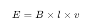
Where:
- E = Induced voltage,
- B = Magnetic flux density (Tesla),
- l = Length of conductor (m) = diameter of the pipe,
- v = Velocity of fluid (m/s).
- The induced voltage signal from the electrodes is transmitted to an electronic converter, which processes the signal, compensates for noise, and calculates the volumetric flow rate using the known pipe dimensions.
Key Features of Electromagnetic Flowmeters
- Requires the fluid to be electrically conductive (minimum conductivity needed).
- No moving parts within the flowtube, giving high durability and low maintenance.
- Can measure both clean and dirty liquids, including slurries and corrosive fluids.
- The flowmeter provides bi-directional flow measurement.
- Accuracy typically around ±0.5%.
Advantages of Electromagnetic Flowmeters
- Low pressure drop since there is no obstruction in the flow.
- Flow measurement is independent of fluid properties like viscosity, density, temperature, pressure.
- Suitable for harsh environments and challenging fluids like slurries, wastewater.
- Available for a wide range of pipe sizes.
Limitations of Electromagnetic Flowmeters
- Cannot measure non-conductive fluids such as hydrocarbons or pure distilled water.
- Requires the pipe to be completely full (no air or vapor pockets).
- Generally more expensive compared to simple mechanical flowmeters.
Applications of Electromagnetic Flowmeters
- Water and wastewater treatment
- Chemical industry for corrosive, slurry fluids
- Food and beverage industry
- Mining and pulp & paper industries
4. Ultrasonic Flowmeters
Ultrasonic flowmeters measure fluid flow velocity using high-frequency sound waves and calculate the volumetric flow rate based on the travel time or frequency shift of these waves as they pass through the fluid.
Working Principle of Ultrasonic Flowmeters
There are two main types of ultrasonic flowmeters based on different principles:
- Transit-Time Ultrasonic Flowmeters
- These use two ultrasonic transducers mounted on opposite sides of a pipe or inserted in the flow path.
- Each transducer alternately transmits and receives ultrasonic pulses through the flowing fluid.
- When fluid is flowing, the ultrasonic pulse traveling with the flow moves faster than the pulse traveling against the flow.
- The flowmeter measures the difference in transit times (tupstream and tdownstream ) of these pulses.
- This transit time difference is directly proportional to the average velocity of the fluid.

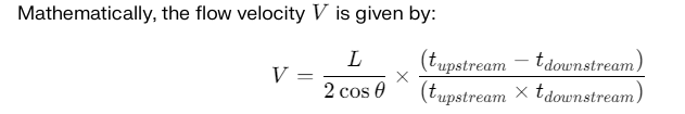
Where:
- L = distance between transducers
- θ = angle of ultrasonic beam relative to flow direction
Since the cross-sectional area A of the pipe is known, volumetric flow Q is:
Q=V×A
- Doppler Ultrasonic Flowmeters
- These rely on the Doppler effect, which is the change in frequency of sound waves reflected off particles or bubbles moving within the fluid.
- The ultrasonic transducer emits sound waves that reflect off suspended particles or gas bubbles.
- The frequency shift of the reflected waves is proportional to the velocity of these particles, and thus the fluid velocity.
- This method requires the fluid to contain sufficient reflectors (at least 100 ppm of particles or bubbles) and is not suitable for pure fluids without suspended matter.
Key Components
- Ultrasonic transducers: Convert electrical signals to ultrasonic pulses and vice versa, made from piezoelectric crystals that vibrate at high frequencies.
- Sensors: Receive ultrasonic echoes and measure transit times or frequency shifts.
- Processor electronics: Calculate flow velocity and convert it into flow rate using the measured data and pipe dimensions.
Advantages
- Non-intrusive: Can be clamp-on type, installed externally without pipe penetration.
- No moving parts: Minimal wear and maintenance.
- Suitable for clean and dirty fluids (transit-time for clean, Doppler for particulates).
- High accuracy and wide flow range.
Summary
Ultrasonic flowmeters use the physics of sound wave propagation in flowing fluids to determine flow rates accurately. Transit-time meters measure flow velocity by timing ultrasonic pulses traveling upstream and downstream, while Doppler meters measure velocity by detecting frequency shifts of reflected ultrasound from particles in the fluid. Each type has distinct operational requirements and benefits suitable for different fluids and applications.
5. Vortex Flowmeters
Vortex flowmeters operate based on the vortex shedding principle, also known as the von Kármán effect. This occurs when a fluid flows past a bluff body (a non-streamlined object) placed inside the flow path, causing vortices—swirling eddies or whirlpools—to form alternately on either side of the bluff body downstream.
Working Principle
- As fluid passes around the bluff body, it separates alternately from each side of the object, shedding vortices that form a repeating, staggered pattern known as the Kármán vortex street.
- The frequency f at which these vortices shed is directly proportional to the velocity V of the flowing fluid.
- Sensors located downstream detect the pressure fluctuations or velocity oscillations caused by these vortices.
- By measuring the vortex shedding frequency, the flow velocity can be calculated, and subsequently, the volumetric flow rate Q is derived using the pipe’s cross-sectional area.
This relation can be summarized by:

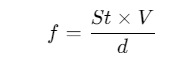
Where:
- f = vortex shedding frequency,
- St = Strouhal number (a dimensionless constant dependent on bluff body shape),
- V = fluid velocity,
- d = characteristic dimension of the bluff body facing the flow (width or diameter).
Components of a Vortex Flowmeter
- Bluff body (shedder bar): The object obstructing flow and causing vortex shedding.
- Sensor: Detects the vortices downstream, often using piezoelectric, capacitive, or ultrasonic techniques.
- Electronics: Processes sensor signals to calculate flow rate from vortex frequency.
Advantages
- No moving parts, leading to low wear and maintenance.
- Can measure liquids, gases, and steam.
- Relatively insensitive to fluid property changes.
- Good accuracy (±0.75% typical).
Applications
Vortex flowmeters are widely used in industrial applications for measuring flow of steam, gases, and liquids where robustness and reliability are important, such as in power plants, chemical plants, and HVAC systems.
In summary, the vortex flowmeter reliably translates the frequency of naturally occurring vortices in a fluid flow into an accurate measurement of volumetric flow rate by exploiting fluid dynamic phenomena.
6. Coriolis Flowmeters
The working principle of Coriolis flowmeters is based on the Coriolis effect, which arises when a fluid flows through a vibrating tube. The fluid moving inside the oscillating tube creates inertial forces that cause the tube to twist or deform in proportion to the mass flow rate passing through it.
Here is a detailed explanation of the working principle:
- Flow Tube Vibration: The flowmeter has one or more flow tubes, often U-shaped or straight, which are mechanically caused to vibrate at their natural resonant frequency by an actuator or drive coil.
- Fluid Flow Interaction: When fluid flows through these oscillating tubes, the inertia of the moving mass causes a secondary force — the Coriolis force — which acts perpendicular to the direction of flow and tube vibration. This force causes the tube to twist or deform slightly.
- Phase Shift Detection: Sensors located at the inlet and outlet ends of the vibrating tube measure the vibration. Without fluid flow, both sensors detect vibrations that are in phase (synchronized). With fluid flow, the inertia causes a time delay or phase shift between the inlet and outlet sensor signals due to the twisting action of the tube.
- Mass Flow Measurement: The magnitude of the phase shift is directly proportional to the mass flow rate of the fluid inside the tube. The flowmeter electronics process this phase shift to compute and display the fluid mass flow rate.
- Additional Measurements: Beyond mass flow, the frequency of tube vibration changes with the density of the fluid, allowing the meter to simultaneously measure fluid density. Temperature sensors can also be integrated for compensation and volume flow calculation.
This principle allows Coriolis flowmeters to measure mass flow directly, independent of fluid properties such as pressure, temperature, viscosity, or flow profile, and makes them highly accurate and versatile for many industrial applications.
Advantages:
- Direct mass flow measurement
- High accuracy
- Suitable for liquids and gases
7. Open Channel Flow Measurement
When flow is in channels open to the atmosphere like rivers or streams, the cross-section varies with fluid level. Techniques include:
- Weirs and flumes: Structures that relate fluid level to flow rate.
- Level measurement devices: Ultrasonic, bubbler, float sensors to measure fluid depth.
- Flow rate derived from level using empirical formulas or theoretical equations Q = KHX, where H is level, K and X constants depending on the structure.
Factors Affecting Flow Measurement
- Fluid properties: density, viscosity, temperature
- Flow profile and velocity distribution
- Pipe size and condition (roughness, corrosion)
- Presence of solids, bubbles, or entrained gases
- Installation and calibration accuracy
Applications of Flow Measurement
- Process control: Ensuring appropriate flow rates of reactants and products.
- Billing and custody transfer: Accurate fluid volume measurement for trade.
- Environmental monitoring: Flow measurement in streams, wastewater discharges.
- Safety systems: Flow detection for leak detection and emergency shutdown.
Flowmeter Selection Guide
Choosing the right flowmeter depends on:
- Type of fluid (liquid, gas, slurry)
- Flow regime (laminar or turbulent)
- Required accuracy
- Pipe size and installation space
- Pressure and temperature conditions
- Budget and maintenance capability
Here is a flowmeter selection guide presented as a table comparing different common flowmeter types based on key criteria:
| Flowmeter Type | Measured Quantity | Suitable Fluid Types | Accuracy | Pressure Loss | Maintenance | Operating Conditions | Advantages | Limitations |
|---|---|---|---|---|---|---|---|---|
| Orifice Plate | Volumetric flow | Liquid, gas | Moderate (~1-3%) | High | Moderate | Clean fluids, stable flow | Simple, inexpensive, widely used | High pressure drop, erosion prone |
| Venturi Meter | Volumetric flow | Liquid, gas, steam | High (~0.5%) | Low | Low | Clean fluids, large pipes | Low pressure loss, durable | Expensive, bulky |
| Electromagnetic | Volumetric flow | Conductive liquids | High (~0.5%) | Very low | Low | Must have conductive fluid | No moving parts, suitable for dirty fluids | Not for non-conductive fluids |
| Ultrasonic (Transit-time) | Volumetric flow | Clean liquids | High (~1%) | None | Low | Mostly clean, no suspended solids | Non-intrusive, clamp-on possible | Not for dirty or aerated fluids |
| Ultrasonic (Doppler) | Volumetric flow | Liquids with solids/bubbles | Moderate (~1-3%) | None | Low | Fluids with sufficient particles | No moving parts, works for dirty fluids | Requires particles or bubbles |
| Turbine | Volumetric flow | Clean liquids, gases | High (~0.5%) | Moderate | Moderate | Steady flow, clean fluids | Good accuracy, wide range | Moving parts, maintenance needed |
| Vortex | Volumetric flow | Liquids, gases, steam | Moderate (~1%) | Moderate | Low | Clean to moderately dirty fluids | No moving parts, wide range | Pressure fluctuations, vibration |
| Coriolis | Mass flow | Liquids, gases | Very high (<0.1%) | Low | Low | Wide range, harsh environments | Direct mass measurement, density | Expensive, limited pipe sizes |
| Positive Displacement | Volumetric flow | Viscous liquids | High (~0.1-0.5%) | High | Moderate | Viscous, low flow | Accurate for viscous fluids | Moving parts, wear |
| Thermal Mass | Mass flow | Gases | Moderate (~1-2%) | None | Low | Clean gases | Direct mass flow, no moving parts | Requires clean gases |
Conclusion
Flow measurement is a critical technology in engineering with a rich variety of methods tailored for different fluids and conditions. Understanding the principles behind flowmeters allows proper selection and accurate determination of flow rates, enabling optimized industrial operations, environmental management, and quality assurance. This detailed article on the basics of flow measurement covers the essential theories, types, units, working principles, and practical considerations necessary for a foundational understanding of the subject.